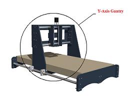
The gantry design is the most popular design in the do it yourself CNC router community. It is popular for a reason, it works. When you build a CNC router, it is important to keep the design trade offs in mind. No matter your budget, the parts you have, or the material you use, there is a design that is best for you.
The gantry design is a proven design for "do it yourself CNC routers." However, there are still many things that you should be aware of.
From a design standpoint, you want your gantry to be stable and balanced. Design the CNC gantry to meet the forces that it will encounter. This will prevent excess stress and strain on you bearings, lead screw, motor, etc.
In order for you to be able to design and build your gantry to meet the required forces, you first need to identify and understand the forces involved.
Lets take a look at the forces evolved with a do it yourself CNC router gantry.
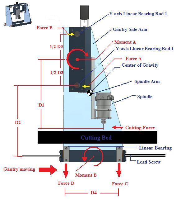 The above image illustrates a side view of a typical do it youself CNC router gantry.
Take a minute to look over the image, there is a lot there. Now lets discuss what is happening. It may seem confusing at first but its rather simple once you understand what is taking place. We will discuss.
Center of gravity/mass
Forces
Moment
Let quickly identify the labels above:
D1 = the distance between the cutting tool (the router bit) and the center between the two Y-axis linear bearing rods/rails (D3).
D2 = distance between lead screw/ linear bearings and the bottom Y-axis linear bearing rail/rod.
D3 = distance between the lower and upper Y-axis linear bearing rods/rails.
D4= distance between the 2 linear bearings that sit on the X-axis linear bearing rods/rails.
Now we will look at the forces evolved.
The Technical Explanation: CNC Router Forces
(scroll down for the short Version)
The image above illustrates a gantry that is moving from left to right as you look at the screen. It is being pulled or pushed by the
CNC drive system
at the bottom. Now, the
router spindle
at the bottom. Now, the router spindle is lowered and it starts cutting.
The cutting action apposes the movement of the gantry resulting in a cutting force. The cutting force varies according to the gantry acceleration, spindle RPM, and the chip load. The chip load depends on the bit you use, the RPM, and the material. We will get into these details when we discuss the CNC router spindle. For now just know you have a cutting force apposing the movement of the gantry.
Just so you know, a force is equal to mass of multiplied by its acceleration. The units of force are lb-f (pounds of force) in the English system or the Newton in the SI system.
The cutting force results in a moment, which is moment A in the figure above. A moment results when you have a force applied at a distance. A moment has units of lbf-in or N-m, we usually call a moment force torque.
Moment A, in the image above, is the result of the cutting force being applied at the distance D1.
Moment A = D1 x Cutting force
Example:
If the distance D1= 12 inches and the cutting force is 5 lb of force. Then the Moment A would be 5lb x 1ft = 5 ft lb of force. ( I converted 12 inches to 1 foot) You can see that even if the cutting force remains the same, the longer the distance of D1 the larger the moment will be.
Moving on, the Moment A results in 2 forces on the Y-axis
linear bearing rods/rails.
These resulting forces are forces A and B in the figure above. Force A and Force B are equal to each other Force A = Force B.
Force A = Moment A divided by 2 divided by ½ of D3 this equals to
Force A = Force B = Moment A / D3
You can see that as the vertical distance between the two linear rods/rails (for the Y-axis linear bearings) grows, the resulting forces A and B shrink which is good. Why is this good? It reduces the amount of centralized torque that is on the gantry itself.
Moment B will decrees as force A decreases.
Moment B = D2 x Force A
Moment B is what causes the whole gantry to rock or want to rotate due to the cutting force. This is not a good thing. You want to decrease Moment B as much as possible. Why?
You want to make have equal amounts of force on your set of linear bearings as possible. This will reduce deformation and chatter in your machine.
There are two ways to reduce Moment B.
1) Reduce Force A
2) Reduce the D3
A well designed machine keeps force C and force D to be as equal as possible. And that is the goal.
Force C and D are the sum of the weight of the machine and resulting forces that occur do to moment B.
We also need to consider the weight of the gantry and try and calculate or guess where the center of gravity will be and keep that directly in the center between the two separated bearings (½ D4). The center of gravity is the point at which the machine would balance.
That is why you often see the gantry upright side arms slanted backwards an a do it yourself CNC router. This compensated for the weight of the spindle which hangs our over the
Y-axis linear bearings.
When you build a do it yourself CNC router, you want the center of gravity of the whole gantry assembly to be directly between the two linear bearings. Or if you have a stationary gantry and a mobile bed, you want center of gravity to be in the center of the bottom of you gantry side arms.
This assures that your machine is balanced and could stand own its own. This applies equal load on your bearings.
The short answer (summary)
When you design or build a do it yourself CNC router, keep the following in mind:
Try and keep the distance between the X-axis lead screw and linear bearings, as close as possible to the bottom Y-axis linear bearing rods/rails. Or as close to the center distance between the top and bottom Y-axis linear rods/rails. (Minimize D2)
Keep the spindle plunge arm on the Z-axis assembly as short as possible and make that arm out of rigid material to prevent flexing. A normal Z-axis arm travel is anywhere from 3 to 6 inches. (Minimize D1)
Calculate or estimate where the center of gravity of the gantry will be located, including the spindle. Design your gantry side arms to compensate and place the center of gravity (CG) between the front and back X-axis linear bearings per arm. (CG should be located at ½ D4 and as close to X-axis lead screw as possible)
Maximize the distance between the upper and lower Y-axis linear bearing rods/rails but still allow for clearance under the bottom rod/rail for your max Z travel. (Maximize D3)
Other considerations
A good gantry design is one of the most crucial factors for a quality do it yourself CNC router. As with all
DIY CNC routers, budget
is a concern which means material are also a concern. Try and visualize and estimate the forces evolved and make your do it yourself CNC router design work with the materials you have.
If you would like a more thorough analysis you may consult us. We offer
free engineering design analysis of your machine.
We can help you find:
Specific CG location
Material stress and strain analysis
Dynamic simulation of your machine
Material selection
And more
Remember, we will discuss more on the gantry design in later section. Topics such as lead screw placement, motor placement, linear bearing attachments, etc. Which are all important consideration with a do it yourself CNC router project.
Now lets take a look at
Step 4: the Z-axis assembly design for the do it yourself CNC router.
Go to Homepage from do it yourself CNC router gantry design