Build your own CNC router Step 2
The Frame and Base
When you design and build your own CNC router, one of the first considerations is the base and frame. Although another practice is to actually design from the top down, but well start at the bottom and work our way up. The Base and Frame Overview
The base and frame of a CNC router is the main structural element of your machine.The base and frame is what holds everything together. This is what will determine your motor placement and lead screw placement along with everything else. The frame and base design will be determined partially by the materials and supplies that you have, the number of lead screws
lead screws
, and motors your budget allow etc. However, we need to become familiar with different designs so that you may buy parts that fit your design. If you can not find or cant afford the parts for the design you would like. Then its back to the drawing board to optimize the design for the materials you do have. This will likely happen a lot when you build your own CNC router. When you look at other homemade CNC router designs, you may notice that almost ever unit is different. Although this is true, you can break down these designs into categories. The X-Axis Base and Frame
When you build your own CNC router, the X-axis frame should also act as the base for the machine as the X-axis should be the axis closest to the ground. This portion of the machine will perform 3 primary tasks.
1) Act as the base for the machine
2) Support the X axis linear motion system
3) Support the cutting table
Lets look at the most common designs for the base. Fully Supported Frame
The fully supported base is one of the best designs and is the design used on most
industrial or professional routers.
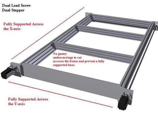
The image above shows only the base and does not show the gantry. Pay no attention to the type of linear bearings. The fully supported design means that both the Y and X axis may rest on the floor or some other structure. There is nothing connecting the gantry across the Y-axis. This allows for a very sturdy design and is not susceptible to the cutting table or the structure itself flexing under its own or external weight. In order for this system to flex or deform, the material itself would need to compress. Keep in mind we are not talking about massive amounts of flex. This all ties back in to the Step 1 on how to build your own CNC router. Where you should already have some idea as to the desired precisions and accuracy you want your machine to hold. A deformation of 0.001 is acceptable if you only expect 0.010 accuracy from your machine. There are drawbacks with this design, the cost. You will need and extra lead screw, lead nut, and motor. You may employ a fully supported frame design with one motor using a pulley and belt system, but you will need to make sure you motor is up to the task. We will cover how to calculate that in the
CNC drive system section.
With this design you can get away with a lighter material as it will be supported against the ground or some other structure. Now lets look at another design.
Fully Supported Frame vs. Fully Supported Bearing Rods/Rails
When we say fully supported in this section, we mean that there is nothing obstructing sweeping across that axis during operation. Later we will discuss fully and end supported linear bearing systems, but that is not the focus in this section. We are focusing on the frame itself. It is possible to have a fully supported linear bearing system and not have a fully supported frame. You can see this in the
Solsyva design below.
Partially Supported X-axis Fully Supported Y-axis Frame
The more common design with most hobby CNC routers out there is the partially supported X or Y-axis.
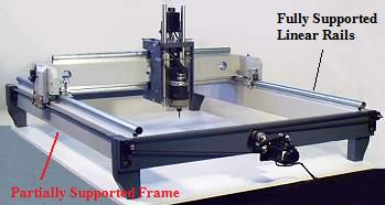
 The image above illustrates a supported Y-axis and a end supported X-axis frame. This is the most common design.
 The gantry would have an undercarriage that would connect the gantry to the lead screw. With this setup you could have a fully supported
linear rails or rods setup.
. However, the rods or rails would still be able to flex with the frame itself. You may only support the frame on the ends since there must be clearance between the ground and the frame to allow the gantry undercarriage to move along the X-axis. In the image above, the Y-axis would be considered supported since you could have a frame that would not interfere with the gantry movement. The frame across the Y-axis would prevent flexing for that axis. This would mean the cutting bed would be very rigid in the Y-axis but could flex or deform along the X-axis. With the design above, even if the frame were made of solid aluminum measuring 1-1/2 by 4-1/2 and the X-axis span were 60 inches, the frame would sag .01 inches in the center, just under its own weight. That does not include the weight of the gantry or anything else. You can understand that this would be an issue if Im trying to design a machine to hole a tolerance of 0.001 in the Z-axis. It is true that the machine would flex as a whole and could be compensated. However, the machine could vibrate and bounce when cutting creating lines in the work. If your machine has a relatively small X-axis span, this design works well and is probably the easiest to setup. There are other solutions.
Partially Supported Y- axis Fully Supported X-axis
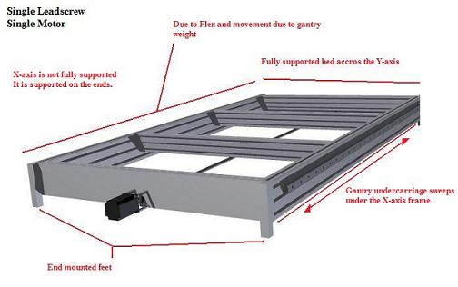
Lets say I have only one motor and lead screw for the X-axis and still wish to maintain a high tolerance on my machine. I could move the
Y-axis gantry assembly
inside the frame which would allow me to fully support the X-axis because the gantry would not cut under the X-axis frame. However in that situation, the Y-axis frame would not be fully supported.
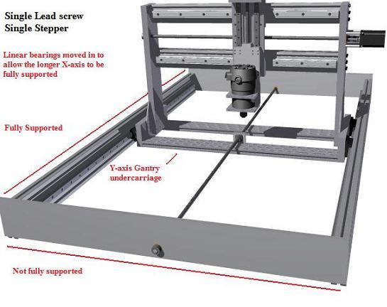 As you can see in this design, the longer X-axis is fully supported (on the ground), however the gantry would cut through any frame in the Y-axis inside the cutting area.
 This means that no matter how much weight I put on the gantry or
cutting table
(not pictured), the X-axis frame would only deform if the material itself deformed. With this design, the cutting bed would need to have its own frame and could sag in the center. However, he machine itself would be constant and once the cutting bed is installed, you could true the cutting table surface by plain the surface with the machine. The cutting bed would then be true to the machine. When you design or build your own CNC router, you need to decide which is more important. Have the machine remain constant or have the cutting bed and the machine flex together. We will cover this more when we discuss the cutting bed.
Alternatives
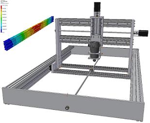
There are other alternatives when you build or design your own CNC router. One way to obtain a fully supported router is to do away with the gantry undercarriage and have the lead screw connect at the top of the gantry or have 2 lead screws high on each side. You may see this application in the Solsyva designs. They offer these blueprints on how to build your own CNC router. However, with a single lead screw up high above the gantry, it makes access to the cutting bed somewhat difficult. This design works well for smaller machines that you wish to be mobile. For instance, a CNC router designed to carve shapes on wood flooring.
The Mobile bed design
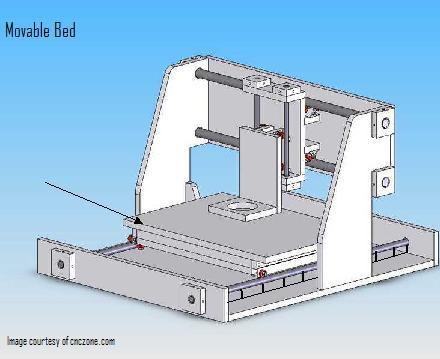
The mobile bed or movable bed design approaches the CNC router frame differently. With a mobile bed CNC router, like the one pictured above, you may have a fully supported frame and bearing system for the X-axis without compromising any structural framing. With this design you also only require one motor and lead screw for the X-axis. Because the lead screw attaches to the bed itself and there is no undercarriage for the gantry, the bearings and frame would not be in the way. This is advantageous because if you want design and build your own CNC router, the chances are you want to save as much money as possible. The bed must also only support its weight and the weight of the material you will be cutting. It does not hold the weight of the gantry itself. However, this design may be inefficient for larger designs as we discussed in step one.
Other Considerations
When you design and build your own CNC router, the material you use to construct the frame will play a big role in the design of the frame. Different materials will deform differently. Keep the material consideration in mind as you choose a frame design. Most popular materials are: 1) MDF 2) Plywood 3) Aluminum Stock 4) 80/20 Structural aluminum. 5) Steel Keep the materials in mind as you think of how to build your CNC router. In later sections of this guide we will discuss bearing placement, lead screw and motor placement, and other design features. All of which should be considered when you build your own CNC router. For now just review and consider your options for the base and X-axis. When you design or build your own CNC router, you may decide to employ some elements from each design. If you try to rush the process and forget to consider these design issues when you build your own CNC router, then you may be setting yourself back. Before you set anything in stone, lets take a look at the
Y-axis gantry and the Z-axis frame assemblies.
Go back to Step 1: How to build a CNC router
Step 3: Designing and Building the Y-axis and Z-axis Frame
Homepage from how to build your own CNC router
We add and edit this information on how to design and build your own CNC router. Stay up to date with our RSS feed.
|


