Building a CNC Router
Step 4: The Z-axis assembly
So far we have looked at the first three steps in building a CNC router
Step 1: Key Design Decisions
Step 2: The Base and X-axis Frame
Step 3: The Y-axis Gantry Assembly
Now lets look at the 4th step,
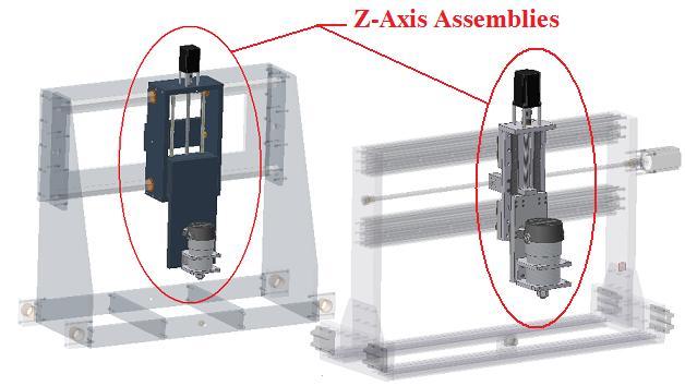
The Z-axis assembly
Below you can see two examples of Z-axis assemblies with the
Y-Axis CNC Router Gantry
in the background.
As with the previous discussions, when designing or building a CNC router it is important to consider the forces that are evolved. That way, you can adjust your design and verify that it will meet
your design requirements
. However, in order to design and build your machine to meet your requirements, you first need to understand the forces evolved.
Forces on the Z- Axis Assembly
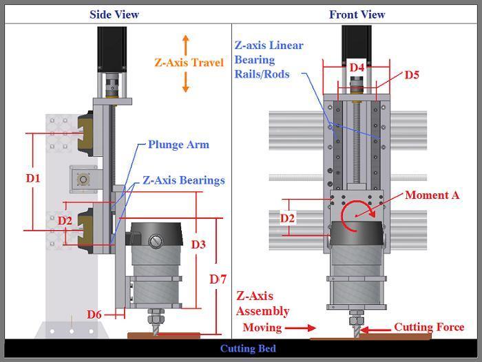
Lets interpret the above image.
The following explains the dimensions:
D1 = the vertical distance between the upper and lower Y-axis linear bearing rods/rails.
D2 = the vertical distance between the upper and lower sets of Z-axis linear bearings.
D3 = the length of the spindle attachment plunge arm.
D4 = the width of the Z-axis assembly.
D5 = the horizontal distance between the Z-axis linear bearing rods/rails.
D6 = the thickness of the plunge arm
D7 = the distance between the cutting force (approx, tip of the cutting tool) and 1/2 D2.
Now that we understand what the dimensions are, lets analyze the forces and moments.
Forces and Moments on the Z-Axis Assembly
Building a CNC router can be easy or hard. Some people over analyze and some people just build it and see if it works. I think the best approach is a mix of the two methods. So lets first try and understand what is happening. The above image illustrates an example of a Z-axis assembly shown in a front view and a side view. Look at the front view and notice that the Z-axis assembly is moving to the right while it rides on the Y-axis linear bearing rails/rods. The plunge arm is at max Z travel and is cutting into a material as it moves from left to right. This cutting action produces a cutting force that apposes the movement of the Z-axis assembly. The cutting force is a variable of spindle RPMs, the number of flutes on the cutting tool, the feed rate, and the material that is being cut. You can learn more on
how to calculate cutting force here
. When building a CNC router an important decision to make is what types of material you would like to be able to cut, which was
covered in step 1.
For now, just understand that there is a force in the opposite direction than the Z-axis assembly is moving. Now lets see what happens because of this cutting force. The cutting force creates a moment, which is illustrated in the image above as Moment A. A moment is just a force that is applied at a distance. We covered moments in greater details in
Step 3.
Moment A = D6 x Cutting Force. Moment A torques the plunge arm in the opposing direction of the cutting force, which torques the whole Z-axis assembly.
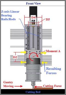 br> This moment results in resultant forces that are applied to the Z-axis linear bearing rails/rods and the Z-axis linear bearings themselves. (Yellow arrows)
As D5 and D2 increase in length, the resulting forces decrease. You can see that when you are designing or building a CNC router, it is important to maximize the horizontal distance between the Z-axis
linear rails
rails (D5), and the vertical distance between the Z- axis linear bearing blocks.
The Plunge Arm
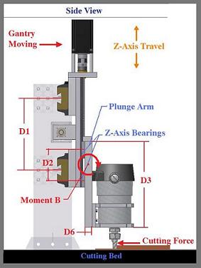
D2 also has an effect while cutting along the X-axis. Take a look at the image to the bellow.
The cutting force causes another moment; Moment B. Moment B is the result of the cutting force being multiplied by the distance between the cutting force and ½ D2. This moment will apply resulting forces on the Z-axis bearings. As the distance between these bearings (D2) increase, these forces will decrease. That is why it is best to maximize D2. As a rule of thumb when building a CNC router, D2 should never be any less that half the length of the plunge arm. Also, you want the thickness if the plunge arm (D6) to be thick enough to not flex under your maximum cutting force.
The flex will depend on the
maximum cutting force
you are designing your machine around, the thickness of the material (d6), plunge arm length (D3), and the material it is made of. If you need help calculating your desired cutting force or the amount of deformation a certain material and size will have, you may
contact us
We offer free
design consultation and other engineering services.
Summary
Keep the following in mind when you design or build a CNC router:
Maximize D1, reduces the forces due to torque caused by the cutting force in the X-axis.
Maximize D2 reduces the forces due to torque caused by the cutting force in the X-axis.
Minimize D3, but still allow for your desired Z-axis travel.
Maximize D4, reduces the forces due to torque caused by the cutting force in the Y-axis.
Other Considerations
In later sections of the
building a CNC router guide
, we will discuss other features such as lead screws, motor placement, linear bearings etc. Dont forget that you may
contact us
with any questions regarding CNC machines in general or your design. We will try and help any way possible. The motor mount that is used in the above image may be bought pre-fabricated from
K2CNC.com
for a variety of
router spindles.
Conclusion
So far we have looked at the first 4 steps when building a CNC router,
Step 1: Key Design Decisions
Step 2: The Base and X-axis Frame
Step 3: The Y-axis Gantry Assembly
Step 4: The Z-axis Assembly
Now lets continue to one of the most important features when designing or building a CNC router system, the linear motion system.
Building a CNC router Step 5: The linear Motion System
Homepage
|


