|
|
|
CNC Control SignalsNow that the components of a CNC controller system have been identified, lets look closer into CNC control though what we will be referring to as command signals. First lets review how the computer or the stand alone user interface communicates to the controller. Most systems today operate on a step and direction format of command signals. Some higher end machines use a proprietary analog or digital signal, but it is usually a variation of the step and direction format. The computer is responsible for generating these control signals. It interprets a language such as G-code into the signals. More will be discussed on the computer and software in the CNC software section. The step and direction signal format describes itself. There are two commands sent to each driver. The step signal and the direction signal. As stated in the
controller component section
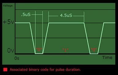
, the signals generated by the computer are 5V DC supplied to the controller via the communication (DB25) or the serial (DB9) port. The communication signals are a square wave form known as Transistor-to-Transistor Logic (TTL) signals. This signal is essentially a series of small pulses ranging from 0V to +5V that represent 0s and 1s in a binary computer language. 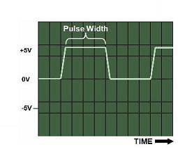
This signal is a form of a Pulse-Width Modulated (PWM) signal where the duration of the pulse is varied to indicate information. The duration of the pulse determines the binary code, either 0 or 1, as communicated by the computer and interpreted by the motor driver.
Each motor driver is different, that is why it is important to understand the command signals and CNC control. Lets look at a popular stepper motor driver for example the
Gecko G201.
The direction signal would be similar but with a minimum of 1uS. For ever 1 received by the step signal input the motor driver would rotate the motor 1 step. The 0 or 1 signal received on the direction side would determine a clockwise or counterclockwise direction. The step signal and the direction signal will be sent simultaneously. The step signal may sit at 0 if no steps are commanded. However, the direction signal continuously streams a direction until the direction changes. Odds are you will not need to know much in regards to the CNC command signals unless working on a homemade driver etc. However, understanding CNC control signals is very helpful when troubleshooting. Next Section: Breakout Boards Return To CNC Controllers |
The Builder's Guide
 Calculators
 CNC Controllers
 |
|
|
[?] Subscribe To This Site
Page Missing?Please bare with us as we upload pages. The website is still under contruction and new content is being added. To see the most recent pages, visit the website blog. Thank you! |
||
|
|
Homepage |
Buyer's Guide |
Builder's Guide |
Contact Us|
© Copyright 2007-2011. |
||
|
|
||