|
|
|
Breakout Boards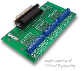
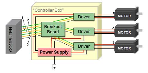
Breakout boards are a common electrical components that take a bundled cable and breaks out each conductor to a terminal that can easily accept a hook-up wire for distribution to another device. They are a common item in electronic projects and enable easy, clean installation of electronic devices. The image at right shows a simple DB25 breakout circuit board from Winford Engineering. The breakout board is positioned between your computer or indexer and the motor drivers and serves two purposes in the CNC control system: circuit protection and signal distribution. Here we will describe the boards function in the CNC control system and what you need to know about how to select one to suit your needs. Lets say, that you have three simple bipolar stepper motors , each with the normal 4 wires. Your wiring schematic would look something like the following:
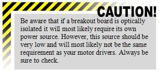
Inside the controller box, we see a direction signal and a step signal being distributed from the breakout cirrus board to each driver. A common ground line is distributed in the same fashion. A power source also distributes power to each driver. Note that there is no power to the board in this system. At left, there are three signal pairs coming from the computer, one for each stepper, and a ground line for the return as indicated by the small black line under the three pairs of signal wires. For a typical DB-25 cable, the ground is the outer jacket of the connector. The breakout board itself may be a smart board, in which the board requires power to do work. An example would be a breakout device with opto-isolators or opto-couplers. These are active devices requiring power, and since the purpose of the board is to isolate the computer, it may not receive power from the computer. This type of board would get power from an external power source. Opto-couplers are small optical switches that isolate circuits to prevent an electrical short from one circuit affecting another. In this case, the opto-couplers protect your computer from a short from your motors or switches. Many high end motor drivers offer their own opto-isolation system. You may also see boards that include their own power distribution internally with fuse protection. This setup is more common on lower voltage systems, such as 12V systems. For these setups, your schematic will look like this:
Breakout boards are handy devices that will often include convenient hookups for other things that you may want to connect to the computer. These signal lines could be any gadget that you want, as long as it can interface with the NC software that you are using. Switches Most machines use limit switches or proximity switches at the limits of travel to prevent the machine from driving itself beyond its own physical limits. Literally, the machine could drive itself off the end of the linear motion system and fall on the floor if you (accidentally) tell it to do so and there are no mechanical stops. As shown below, the limit switches would connect to the breakout board directly. 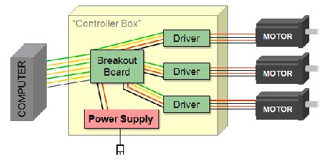
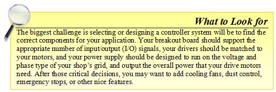
Summary The selection of the breakout board should be one part of a larger effort to find compatible components. The key features that you should look for regarding breakout devices selection should be: Connector Type Breakout circuit boards are a common item to electronics, and not specific to the CNC industry. There are literally thousands of them from which to choose. In most cases, you will want a setup with a female DB25 computer cable connection on one end, and screw-post terminals on the other. Number of I/O Signals In most cases, the DB 25 cable interface will give you as many as 24 I/O signals and one common ground. If you exceed this capacity, you may want a second breakout device connected to the DB9 port on your computer. For a discussion on hooking up your board, please
see the breakout board hookup section.
Feature Some boards are specifically designed for CNC devices and offer nice features that enhance your machine.
Next Section: Breakout Boards Hookup |
The Builder's Guide
 Calculators
 CNC Controllers
 |
|
|
[?] Subscribe To This Site
Page Missing?Please bare with us as we upload pages. The website is still under contruction and new content is being added. To see the most recent pages, visit the website blog. Thank you! |
||
|
|
Homepage |
Buyer's Guide |
Builder's Guide |
Contact Us|
© Copyright 2007-2011. |
||
|
|
||