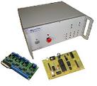
CNC breakout boards
DB-25 and DB-9 pin assignment
CNC Breakout Boards
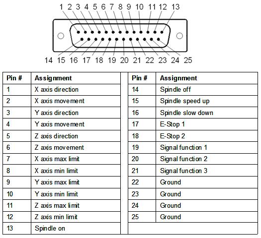
The following section shows how DB25 and DB9 ports are numbered. The breakout boards should have documentation that will tell you which terminals correspond to which pin locations on the cable between the computer and the CNC breakout boards. This cable will be the 25-pin printer cable for most homebuilt applications. This connection is know as a DB25 plug, but on rare occasions where you have a lot of devices on the machine, you may also need to use the computers DB9 plug, which has, you guessed it, 9 pins. The pin locations are numbered so that you can keep track of which conductor goes where. The numbering for the DB25 connector will be as follows:

Similarly, the DB9 will be numbered as:
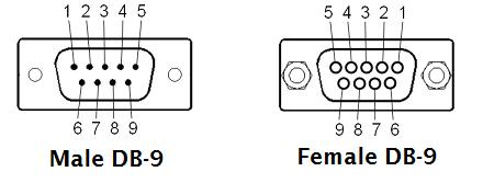
Any computer supply store may have these cables if you need to acquire them. Even your local super-mart may carry them
To this point, you should know: - Stepper motors need two pieces of information: step direction and number of steps to take. - Each signal has its own pin location on the DB25 plug. - At least one of these pins should be the ground. - A single cable from the computer can be used to communicate motor movements, limit switches, and other auxiliary information. So now lets look at an example pin out on a DB25 plug. In the table below, we have three stepper motors, three pairs of limit switches, spindle on/off, spindle speed adjustment, two emergency stops, and signal functions left over that were not used. The remaining pins are grounded. The DB25 numbering has been repeated for your reference. Example Pin Out:
Return to CNC Controller
Home
|
