|
|
|
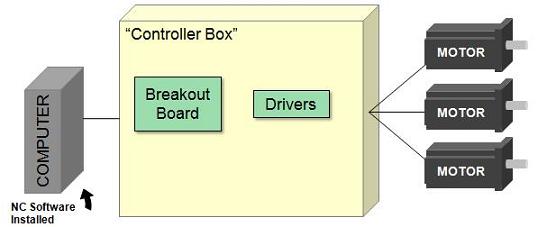
The CNC Controller ComponentsThe CNC controller components work together to interpret positioning signals created by a computer and NC software into precise motor control. This page will explain the function of each of the controller components and how they work together to make a controller system.The Components The Power Supply Unit The same conditions are true for CNC devices. They require a low-voltage communication line, through which the computer tells the machine what to do, and a power source that provides the power for moving, cutting, and other such operations. A power converter, usually referred to as the power supply unit (PSU), is often used to change the form of the supplied power from alternating current (AC) from the power grid, to direct current (DC) that is more easily used by the machines drive motors. The power supply handles large voltages and currents that could be harmful to the NC circuitry. Therefore, the power source, motor drivers, and motors are often separated from the computer with a circuitry protection system that isolates surges in electrical power. The Circuitry Protection System A low-voltage communication signal passes from the computer through the breakout board unchanged to the motor drivers. This isolated your computer from the CNC controller circuit but allows the signals to carry through to your motor drivers. The motor drivers As a note, the computer is fully capable of connecting directly to the drivers and driving the motors, but this setup puts your computer at risk. The first figure is an idealized block diagram of your CNC electrical system. A little more detail has been added in the figure below to show the conceptual layout of signal wires (light black) and power wires (heavy black). 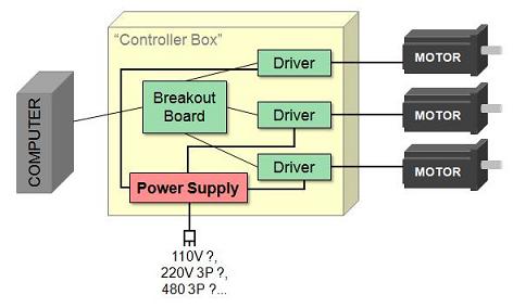
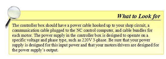
Although your computer will run on 110VAC, the CNC machine may run on 110VAC, or 220VAC, or 480VAC, and may be single phase, three phase, etc This power enters the controller box and will be distributed by the power supply. For most machines, the power supply will convert the incoming power from alternating current (AC) to direct current (DC). This DC supply will be of a lower voltage, such as 12V, 24V, 36V, or higher. The power supplied depends on you CNC controller components, specifically the motor drivers.
 The "Signals"
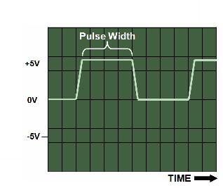
The signal lines coming from the computer operate on 5V DC supplied by the computer communication port, and is a square wave form called a Transistor-to-Transistor Logic (TTL) signal. This signal is essentially a series of small pulses from 0V to +5V that represent 0s and 1s in a binary computer language. This signal is a form of a Pulse-Width Modulated (PWM) signal where the length of the pulse is varied to indicate information. The width of the pulse determines the binary code sent; either a 0 or a 1 as communicated by the computer and interpreted by the motor driver. More on the signals may be found in the signals page. The signal from the computer to the breakout board is the same as that from the breakout board to the motor driver. Remember, the breakout board provides circuit protection and signal distribution. Therefore, the signal coming out of the breakout board is also a 5V TTL signal of the same form. However, as discussed previously, the signal after the driver has been conditioned as needed to provide the large move voltage and current needed to drive the machine. 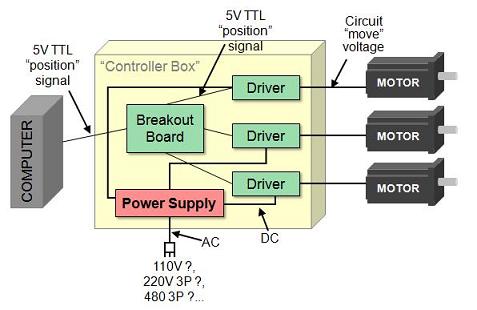
Summary of CNC Controller Components By now you should have a decent understanding of the CNC controller components and their function. The computer generates the signal which passes through the breakout board. The motor drivers and limits switches hook up to the breakout board. The power supply unit provides the correct voltage and current required by the motor drivers and the motors. The motor drivers receive the position signals from the breakout board and supplies the correct power to the motors to make them rotate to the correct positions. If you are buying a CNC controller unit all of these components should be included, but always check. If, are trying to assemble your own controller unit by buying the CNC controller components separately, be sure check the specifications of the controller components to ensure compatibility.
Go to Home from CNC Controller Components |
The Builder's Guide
 Calculators
 CNC Controllers
 |
|
|
[?] Subscribe To This Site
Page Missing?Please bare with us as we upload pages. The website is still under contruction and new content is being added. To see the most recent pages, visit the website blog. Thank you! |
||
|
|
Homepage |
Buyer's Guide |
Builder's Guide |
Contact Us|
© Copyright 2007-2011. |
||
|
|
||